60% Electrocapacitive (EC) Keyboard

Kindly provided by Niz.
Introduction
After reading a Github repository about designing your own Topre keyboard a while ago, designing one has been on my to-do list. My months of on-off google searching tells me that the only way for you to source the springs is to get one from a donor Topre board. I didn't think that was sustainable and that put me off designing one. The sliders, housings, and rubber domes can be bought from Niz, so the springs were really the missing component.
After a long while of forgetting about the whole thing and re-reading the repo again, I came across AA battery spring that could potentially work. I did a quick google search for Topre spring dimensions and came across this reddit thread. It wasn't the exact dimensions, but it's small enough that it could fit.
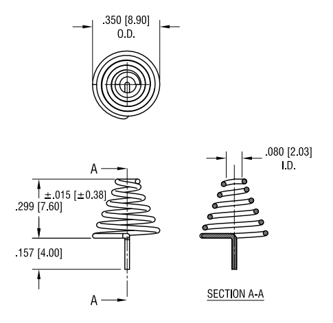
At just $6.30 for 100 pieces already, this seems like a nice sustainable source of conical springs that, if it worked, then would mean cheap EC keyboards.
I went and designed an EC keyboard that I thought would be special: an Alice layout EC keyboard.
Someone suggested I contact Niz to see if I they're willing to provide springs for the project, so I gave them an email with the images linked above and my intent. After some back and forth emails where they asked me about past projects I've done and me showing my blog (hehe), they asked if I can do a 60% keyboard similar to the GH60. I said, sure and after 24 hours, I had a new PCB layout made.
The EC GH60
The PCB
I basically just followed the custom Topre guide I linked above exactly. I went with the same parts, too. I basically trusted that all the info on the guide worked. I mean, of course it made sense when I was reading it, but I had no idea if it was really going to work, especially the PCB layout I made.
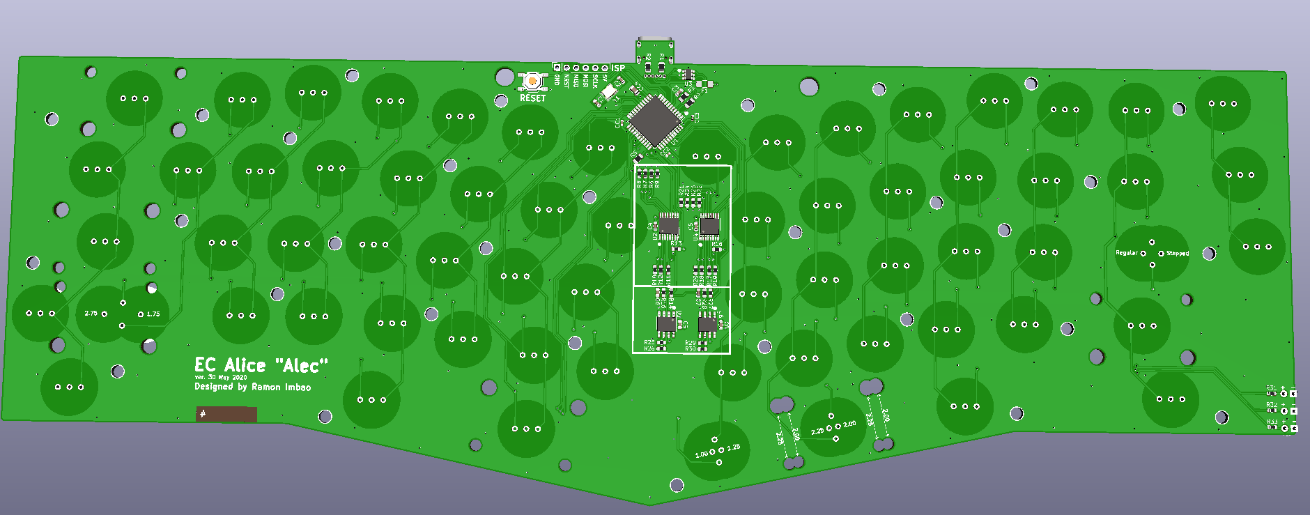
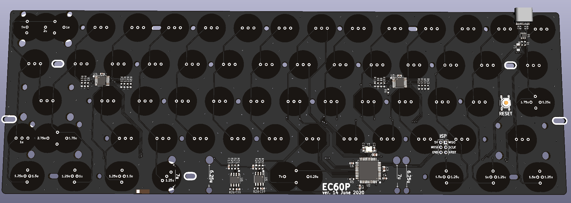
The PCB (as well as the EC Alice) is a 4-layer board. The guide states that 2-layer can work but I wanted the best chances for the PCB to work, so I opted for 4 layers. It was quite a nice experience routing things though. No more long power traces – just plop a via down and you're done! Well, I'm not sure about best practice but I did watch a few YouTube videos about PCB RF layout. I'm basically a pro. 😎 (lmao no)

I decided on supporting split backspace, split right shift, and standard/Tsangan bottom row for the key layout. Supporting ISO is an ugly mess even on MX boards so I decided not to. Every position that has overlapping keys basically has their own custom footprints. I think it's six total custom ones apart from the required ones like 1U, 1.5U, etc.
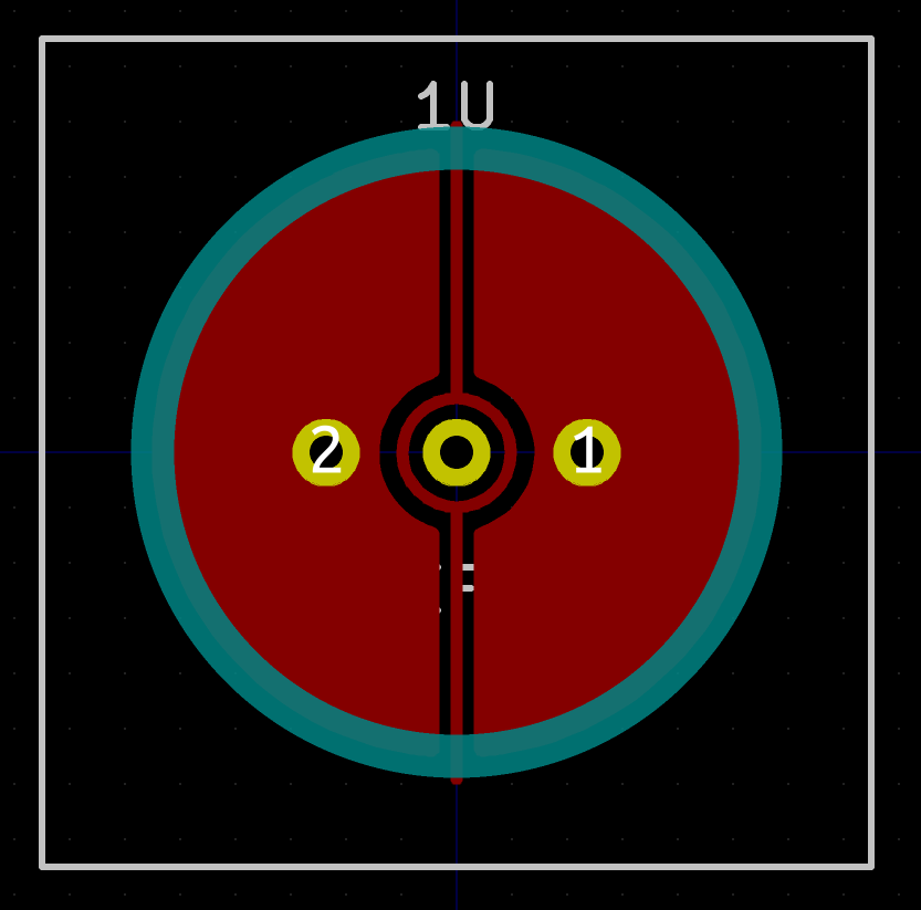
The shape of the pads were made in Fusion 360, and exported as a DXF file. I imported those into Inkscape and exported them as PNG files with crazy resolutions (1000×1000++) for an 18mm × 18mm footprint. I still kept the solder pad for the Keystone AA battery spring instead of just straight up going with Niz springs because I was too lazy to edit my footpritns.
After I had shown Lam (my contact at Niz) the PCB and iterating and re-iterating that I was totally not sure that this was even going to work. They agreed to sponsor the project. They would send over two PCBs and enough parts to build one.
Initial build and assembly
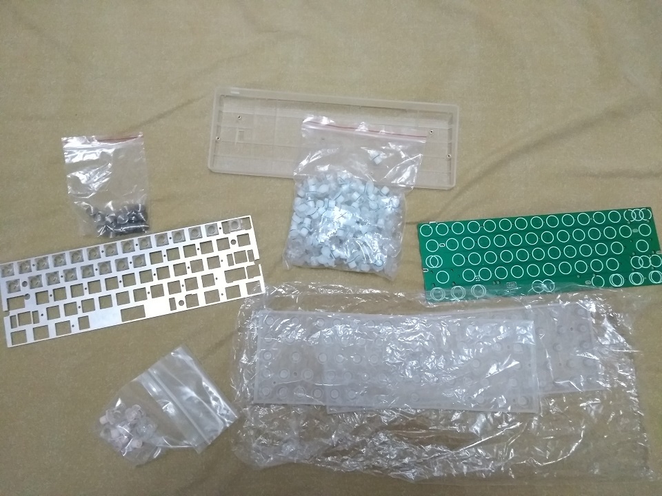
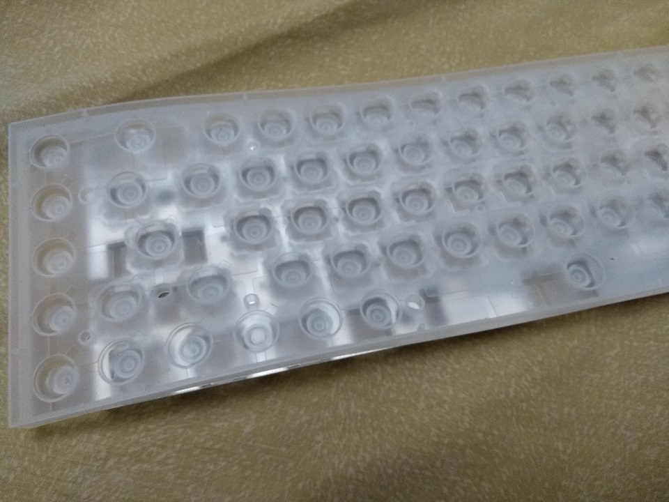
The parts arrived after a week of delay from FedEx. (I mean, we are still under lockdown) They all came in an elegant, minimalist-looking black box. Included were the sliders, housings, conical springs, two rubber domes (for a 65% though), a custom plate, the two PCBs, and a clear 60% case.
The PCBs were ordered from JLCPCB, so everything but the USB connector was populated. That was the first thing I soldered. Not sure if my iron needs a new tip or because of the 4-layer board but it seemed more difficult than usual, even with flux. I thought I'd been able to solder the mounting legs, but then turns out it was a cold solder joint. I managed to do it anyway. Good thing I didn't wreck any PCBs. Would've felt really bad, man.

Because the USB connector overlaps slightly with the EC pad, I placed some kapton tape on the mounting pads where the springs would sit just to prevent the spring shorting to ground. The spring might not be able to couple with the capacitance made by the pads.

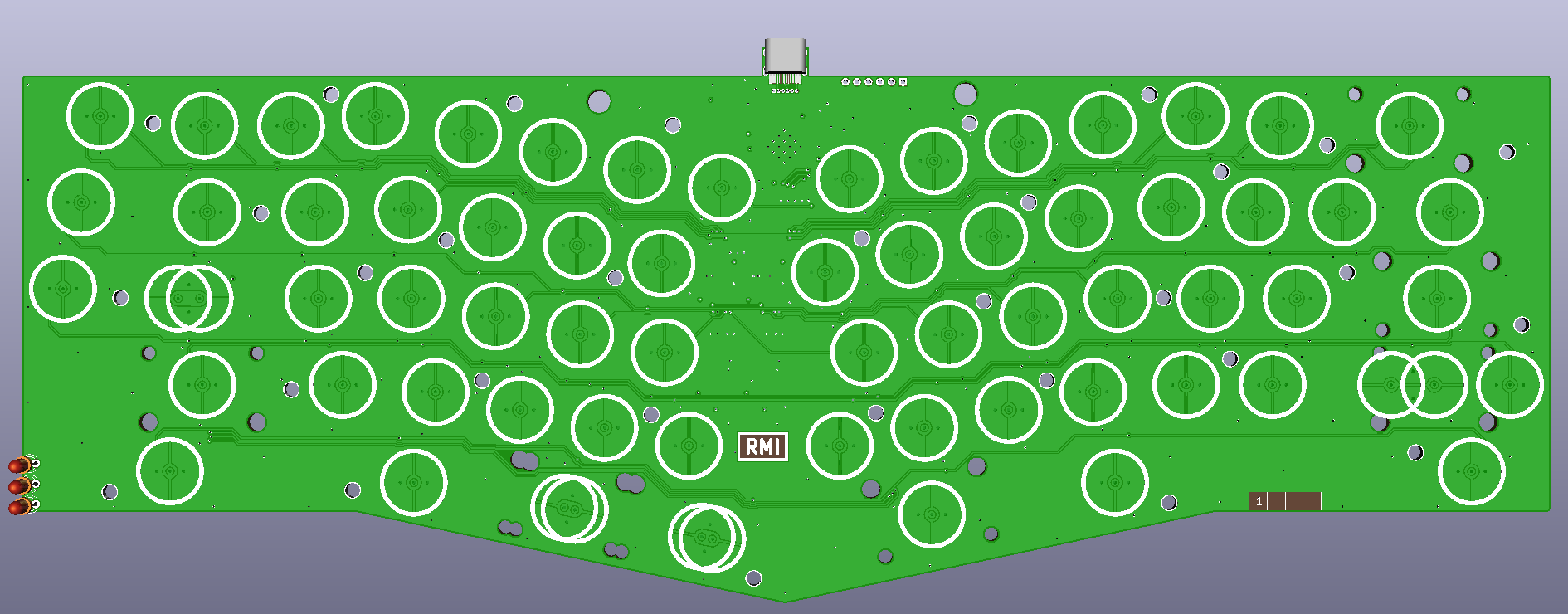
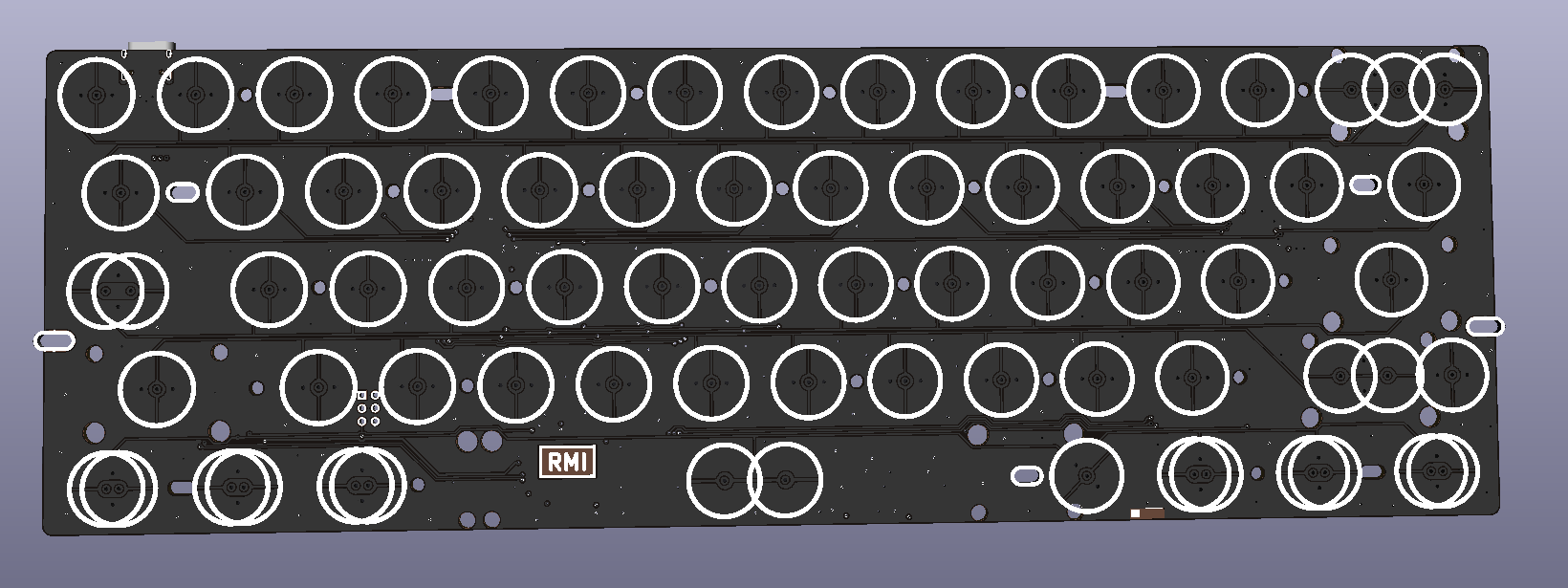
The guide doesn't mention it, but I've seen it in some teardown photos of Niz EC PCBs, but there seems to be holes for mounting the PCB to the plate. I wasn't sure where to add them, so I added them in both the PCB and the custom plate seen above. See all the tiny holes in between switches? Definitely overkill. Niz should make a proper 60% rubber dome for this project and then I'll match that on the PCB and plate instead.
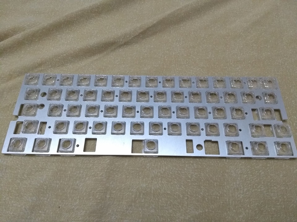
Here, I'm testing the fit of the housings on the plate, but of course the domes don't fit since they sent over a 65% rubber dome sheet.
I test fitted it in the case as well and found that the padding around the domes would not let it fit in the case, so I had to trim those too.

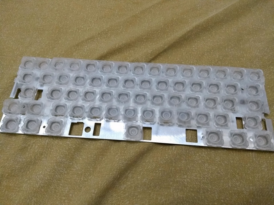
Here's when I really started trimming the domes. I had to separate sections from the whole sheet so they can fit, and I had to cut out sections for the stabilizer holes. Niz uses costar stabilizers for their keyboards, but I am using MX-style stabilizers for mine. I kept doing test fits every step of the way and this is when I encountered a problem with the housing: it would collide with the MX stabilizers. I don't think it would also work with plate-mount MX stabilizers so maybe that's why Niz opted for costar?
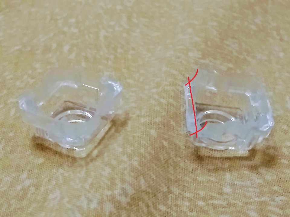
I trimmed off the front parts of the housing (highlighted in red above) so the stabilizer can fit between the housings when mounted.
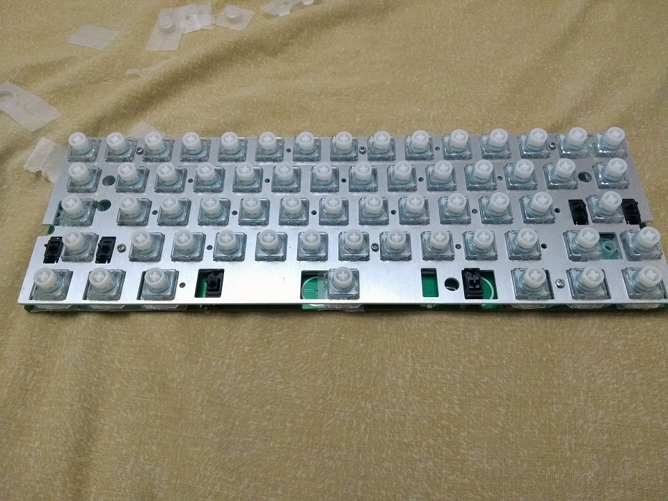
After that, it was all smooth sailing. It takes a while to put the springs on the domes (especially since they're not a single sheet), and I had to use some relatively long M2×10 bolts to secure the case. It's even held together by just a nut underneath the PCB. I have to rethink the design to make it nicer to secure.
The results
I wrote some experimental code while designing the EC Alice keyboard. I just adapted it for the EC GH60 keyboard. Of course, it didn't work the first time. It never works the first time! Long story short, after some head scratching, review, and a bit of chatting with people on Discord about it, I got it to work a bit!
It's still very much not working as intended. The ADC only measures 50 when not pressed and 90 when pressed (when it should be ranged 0-1023). I might need to change the values for the op-amp. The guide sets it to around 200. I ordered some 0603 parts to play around with some values and see if I can improve it. If I can improve it, I'll ask Niz if I can get another prototype PCB, but hopefully this will be the final one.

After getting one button working, I got it working for one column. I refactored the code a bit more to make it generic and all I'll change is the config.h file. But afterwards, I got it to work for 4 columns. When I do all 14 columns, it doesn't register keypresses anymore, so I guess I'll wait for my new parts to arrive before I try again.
Remarks
This is the blog post 1/N about this keyboard. I'll be posting more regarding this keyboard project in the future once I've made progress, but this is looking really good!