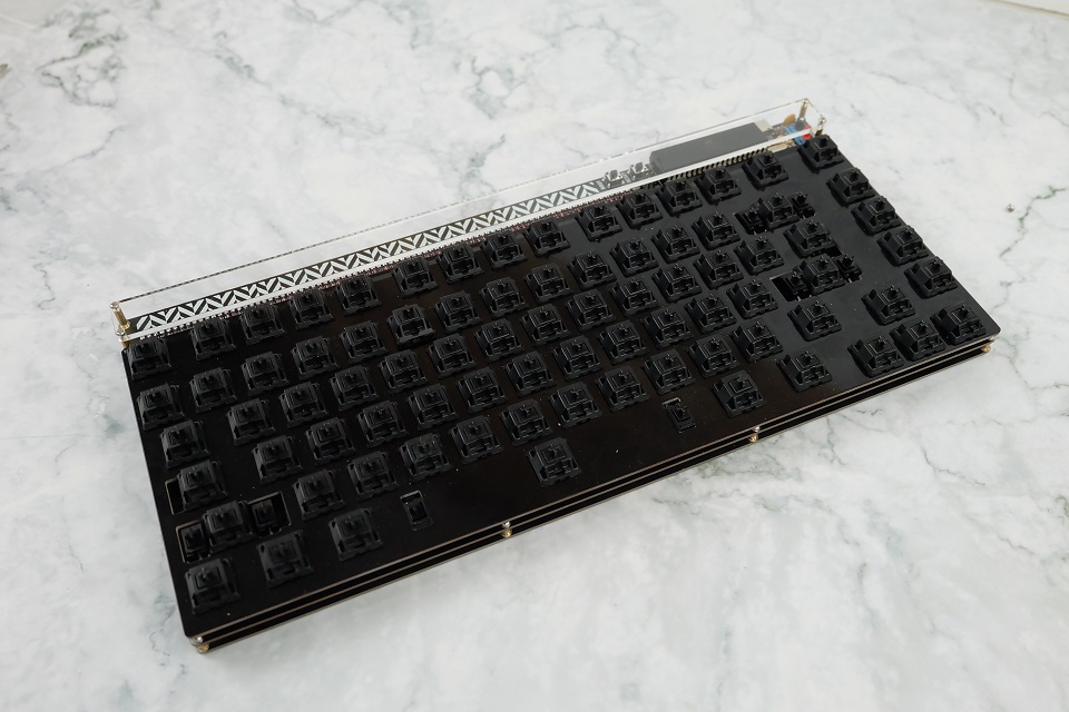
Through-hole 75% Keyboard 'Herringbone'


Description
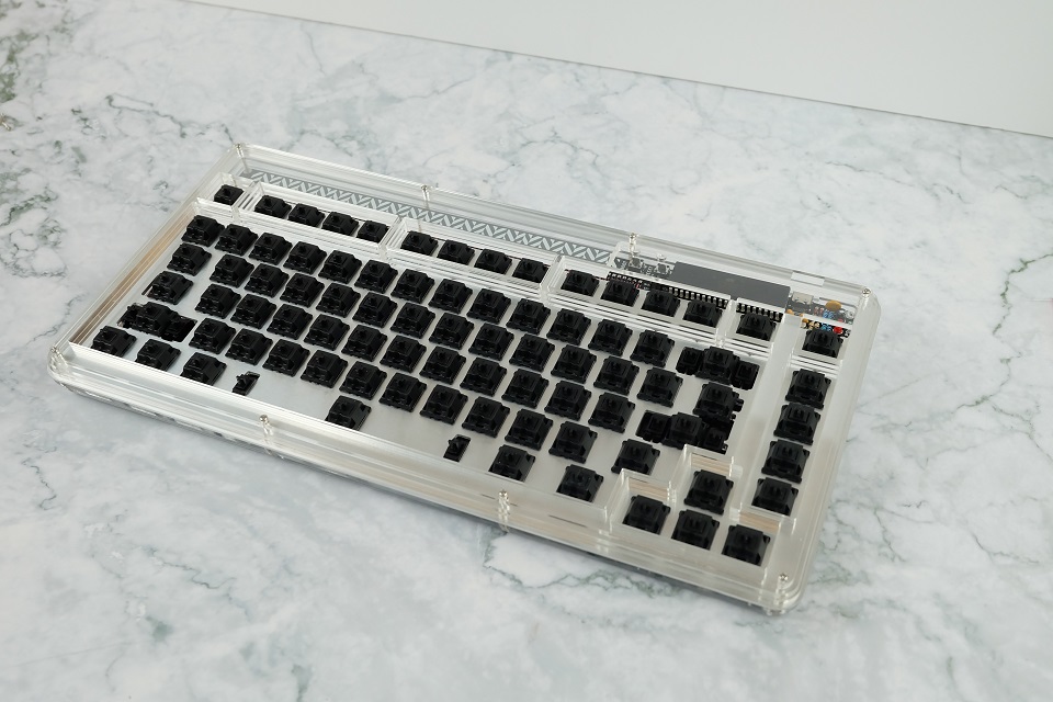
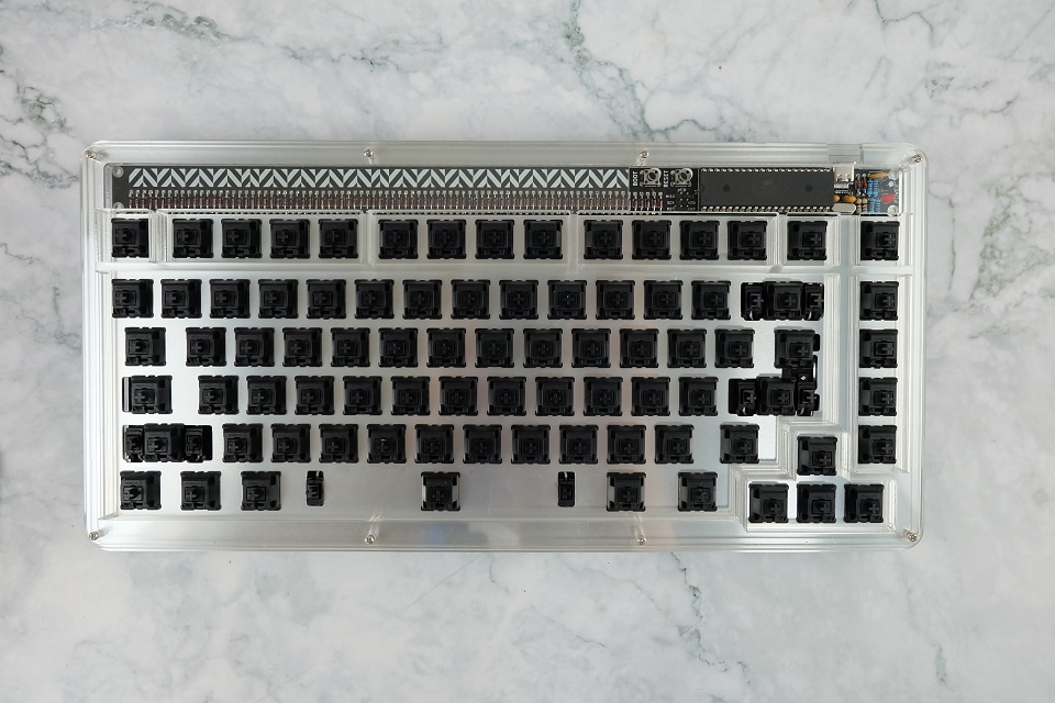
Inspired by Plaid, Gingham, I present to you the Herringbone keyboard: a 75% through hole keyboiard kit!
Layout
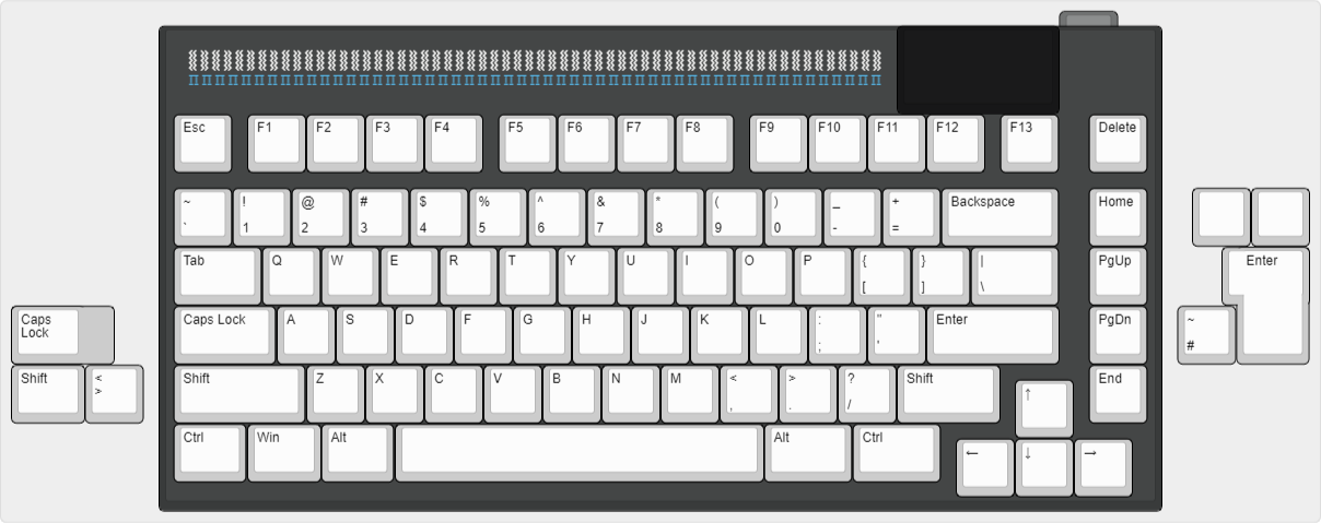
This time around, there's only a few layouts supported by the Herringbone: split left shift, split backspace, and ISO enter. There is an extra F13 key at the F-row (that I mapped to Print Screen on the default layout). While building the keyboard, I thought to myself I should have included the option for 1.5-1.5-7-1.5-1.5 for the bottom row. Maybe for a Herringbone V2? 👀
Build Guide
This section is for the participants in the group buy. Just like the Wete, it's a straightforward build, and I just want to highlight the order you want to go through when soldering all the components (and there are a lot to be soldered!)
Unboxing
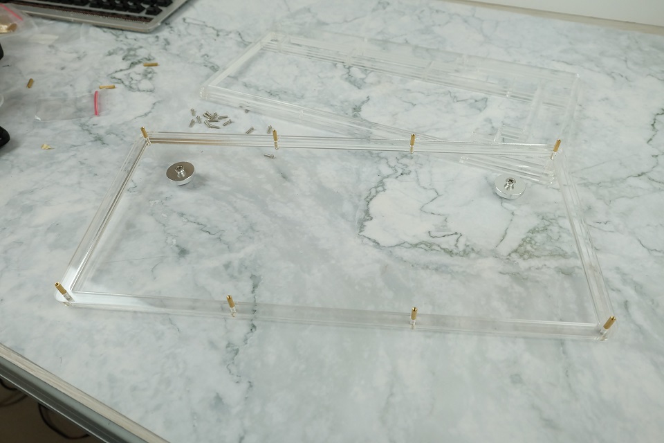
Depending on which kit you ordered, you will receive either the PCB skeleton case in parts or the acrylic case semi-assembled. If you received the acrylic case, simply unscrew the eight screws at the top and separate all the acrylic pieces.
Soldering the Components
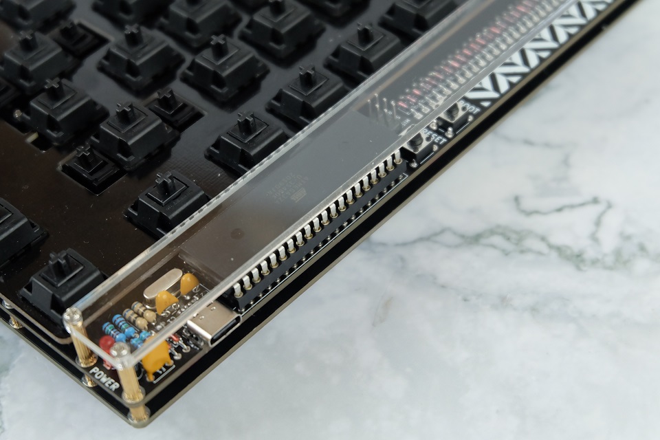
The meat and potatoes of the build. Whether you have the low profile or high profile kit, check that you have the components listed below:
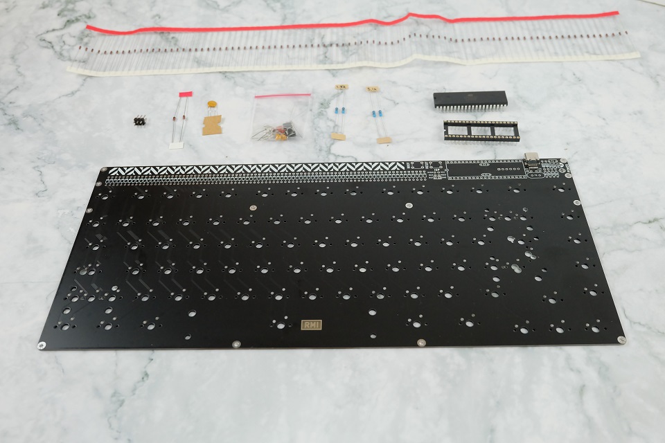
From top to bottom, left to right:
- Long tape of diodes (1N4148)
- 2x3 male header
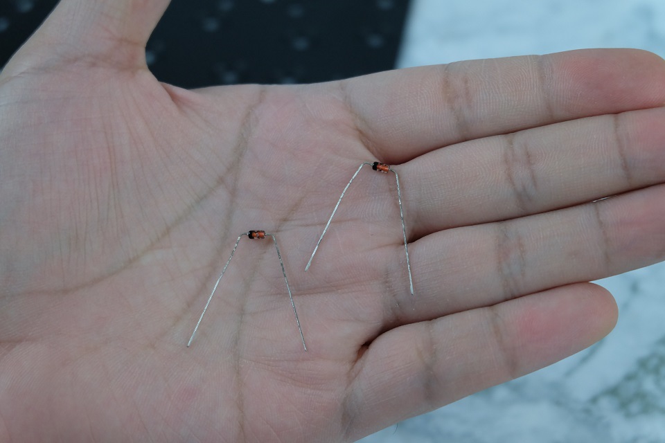
- 2× 3.6V zener diodes
- Fuse
- Bag of loose components, with:
- 16 MHz crystal
- 3mm red LED
- 2× 22pF capacitors
- 2× 68Ω resistors
- 2× 100nF capacitors
- 10µF capacacitor
- 2× tact switches (NOTE: High profile users will get two extra ones with longer stems)
- 2× 1.5kΩ resistors
- 2× 5.1kΩ resistors
- ATmega32A IC
- 40-pin IC socket
- Main PCB
We'll be doing the lowest components first, and then moving on to the taller components.
3.6V ZENER DIODES
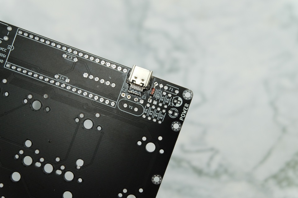
We'll start with the components near the USB connector, beginning with D2 and D3. These use the 3.6V zener diodes. These are the two diodes separated from the long tape of diodes. Do NOT mix these up!

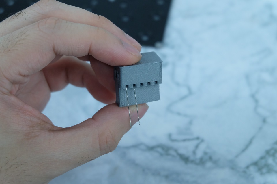
Included with the kit is a small diode bending tool. Place your diodes inside the thinner tool like seen below.

Place the wider tool on top and press down.

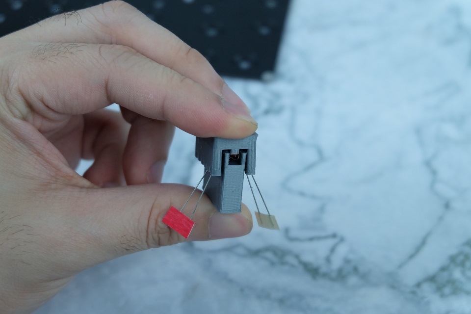
Finish it off by removing the tape, and extracting the diodes from the tool.
The technique also applies to the 1N4148 diodes we'll be doing later.
Finally, place the zener diodes in the components marked D2 and D3. Orientation is important! The black bar on the diode should align with the bar in the symbol on the PCB. These diodes should have the black mark on the bottom.
After placing the components in the hole, bend the legs on the underside a bit so they don't fall out when you flip the board.

Solder the pads from the underside, and trim the legs with a flush cutter.

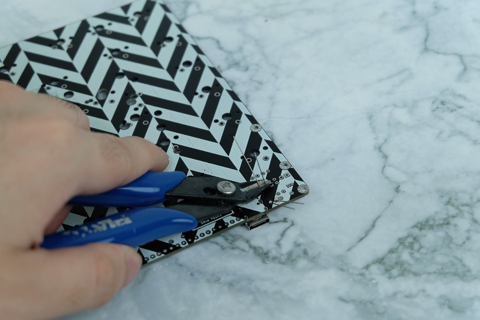
NOTE: This process of bending, placing, bending outward, soldering, and trimming applies to the rest of the components.
5.1kΩ RESISTORS
Next up are the 5.1kΩ resistors. These come in a tape. These go in the components marked R5 and R6. Orientation does not matter.
Unfortunately, you can't use the diode bending tool to bend the resistors.
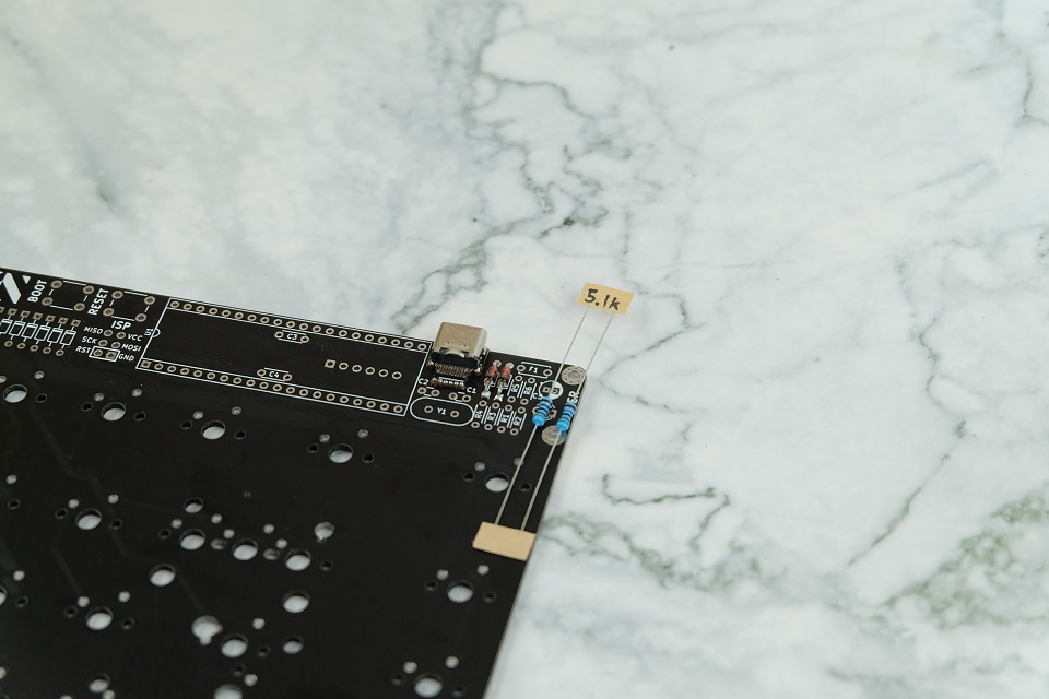
Remove the tape, bend them at the innermost edges of the legs slightly inwards, place them in the hole, and then do the bend-solder-trim. Make sure that the leg of the resistors do not touch the other components later.
1.5kΩ RESISTORS
Next are the 1.5kΩ resistors. These come in a tape. These go in the components marked R1 and R2. Do the same thing as with the 5.1kΩ resistors. Orientation does not matter.
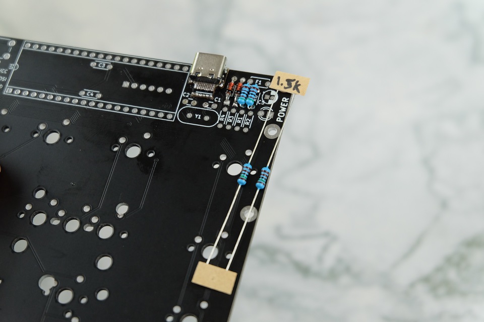
Again, after installing the resistors, make sure that the legs don't touch other legs.
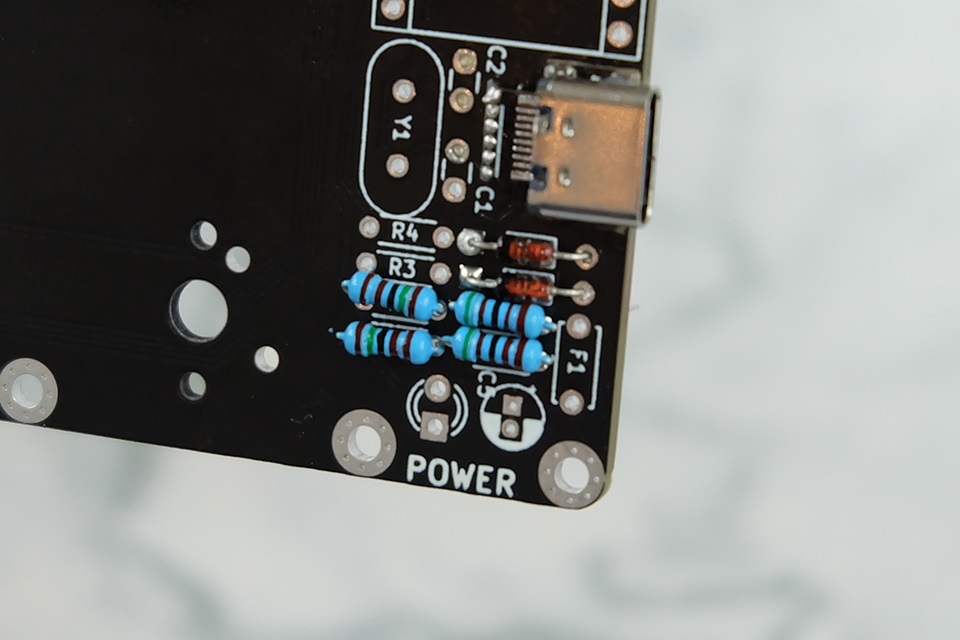
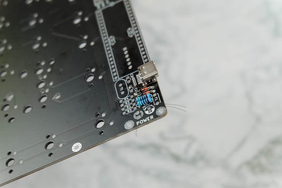
68Ω RESISTORS
Next are the 68Ω resistors from the bag of loose components. These go in the components marked R3 and R4. Orientation does not matter.

Again, make sure the legs don't touch other legs!

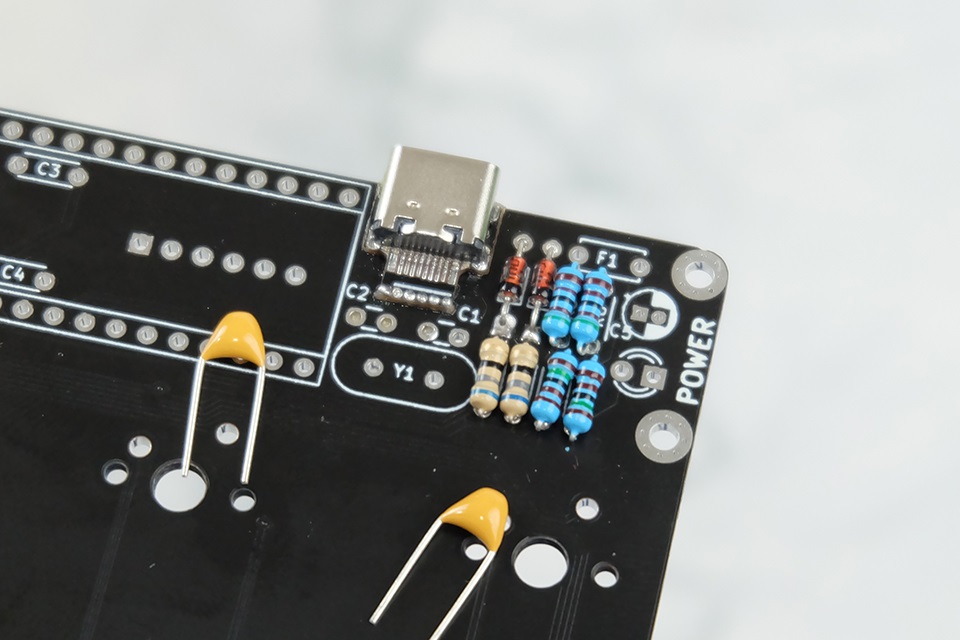
22pF CAPACITORS
Next are the 22pF capacitors from the bag of loose components. These go in the components marked C1 and C2. Orientation does not matter.
When soldering make sure the legs do not touch the USB connections above. Don't touch those with your iron too, or bad things will happen.
16 MHz CRYSTAL
Next is the 16 MHz crystal from the bag of loose components. This goes in the component marked Y1. If it keeps falling out when you flip, you can use tape to hold it down before soldering.

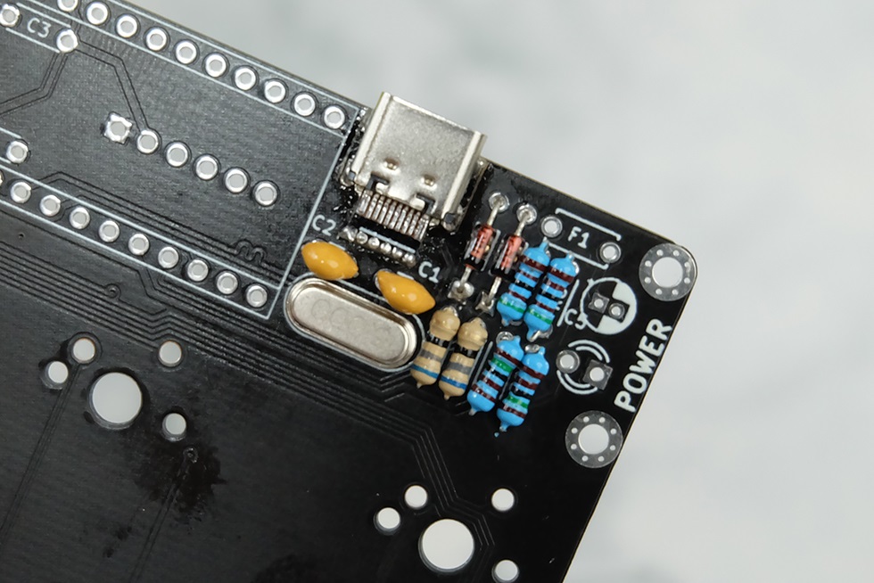
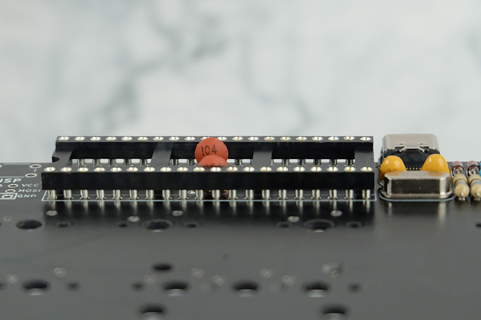
100nF CAPACITORS
Next are the 100nF capacitors from the bag of loose components. These go in the components marked C3 and C4. Orientation does not matter.
You may have to bend the legs outward a bit before inserting. Make sure it's as flush as possible to the PCB and that it's perpendicular after mounting.

40-PIN IC SOCKET
Next is the 40-pin IC socket. Orient the socket such that the U-shaped cutout aligns with the U-shaped symbol on the PC (near the U1 marking).
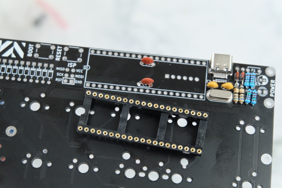
I like soldering the corners first to tack the socket down before soldering the rest of the pins.


NOTE: Do NOT spend too much time on one pin or you risk overheating it, melting the plastic and causing the pin to fall off!
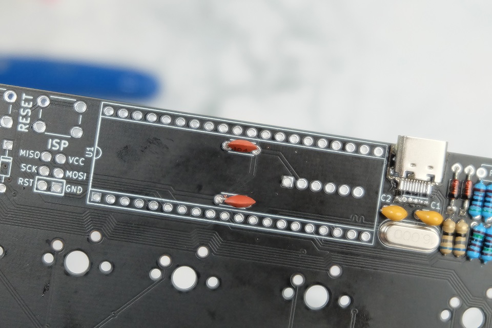
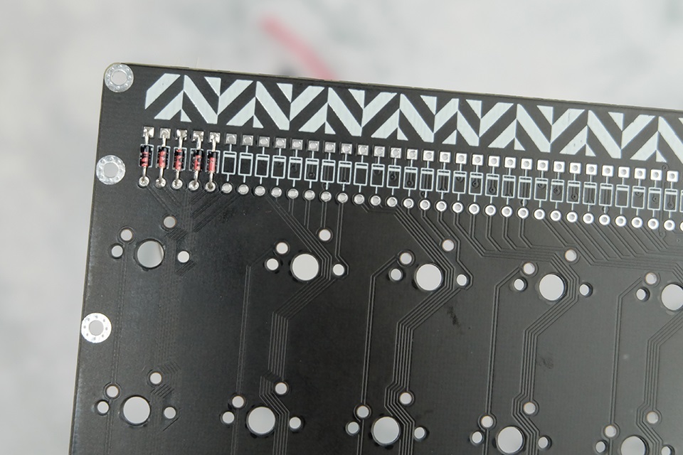
1N4148 DIODES
Next are the 1N4148 diodes, the ones that came in the long tape. These do not have markings but are the ones right beneath the herringbone pattern starting from the left side of the PCB. Orientation is important! Match the black mark on the diode with the mark on the PCB. The black mark should be on top for all the 1N4148 diodes.
Do the same technique as seen in the 3.6V ZENER DIODE section for bending, soldering, and trimming the diodes. Don't forget the diode bending tool! It's up to you if you want to place all of them, then solder and trim, or do it five at a time like I did.

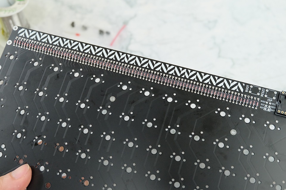
It's easy! Just really tedious.
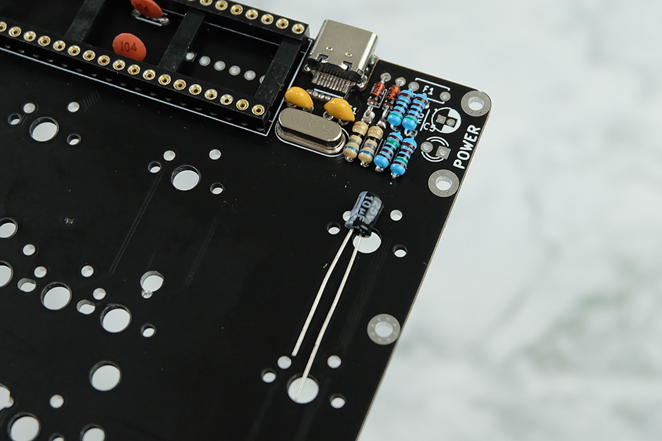
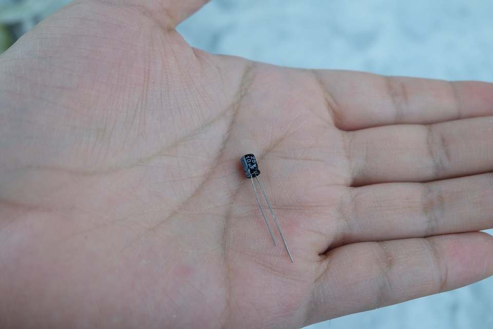
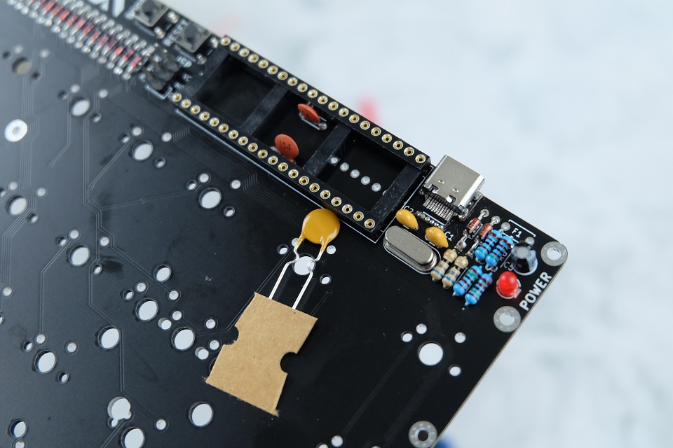
10µF CAPACITOR
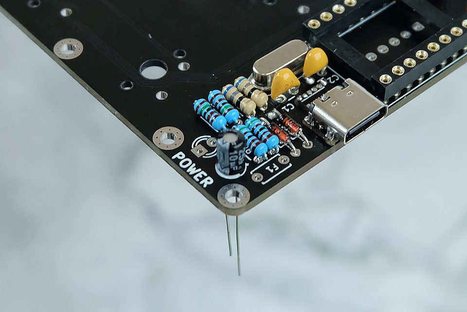
And back again to near the USB connector. Next is the 10µF capacitor in the loose bag of components. Orientation is important! The white band on one side of the capacitor (which marks that side as negative) should align with the filled side on the symbol on the PCB.
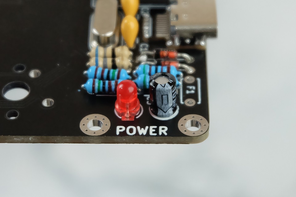
3mm RED LED
Next up is the 3mm red LED. Orientation is important!
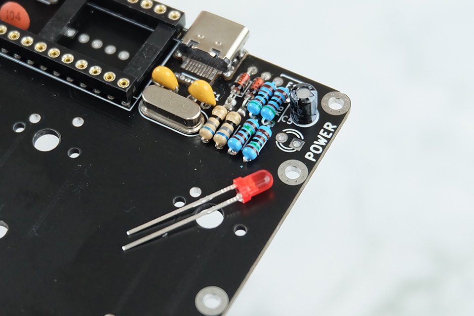
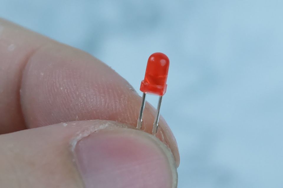
Insert the LED such that the negative leg goes into the square hole.
TACT SWITCHES
Next up are the two tact switches from the bag of loose components.
NOTE: High profile case owners can opt to use the buttons with longer stems. This makes it easier to press the button when there's the high profile case.
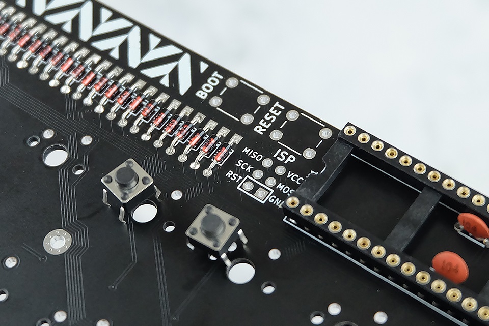
There is absolutely no way for you to insert this wrongly. You should never force the button to be in any position. It will go in the hole easily and stay in there while you solder.
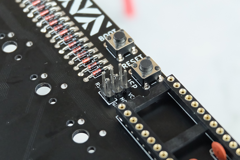
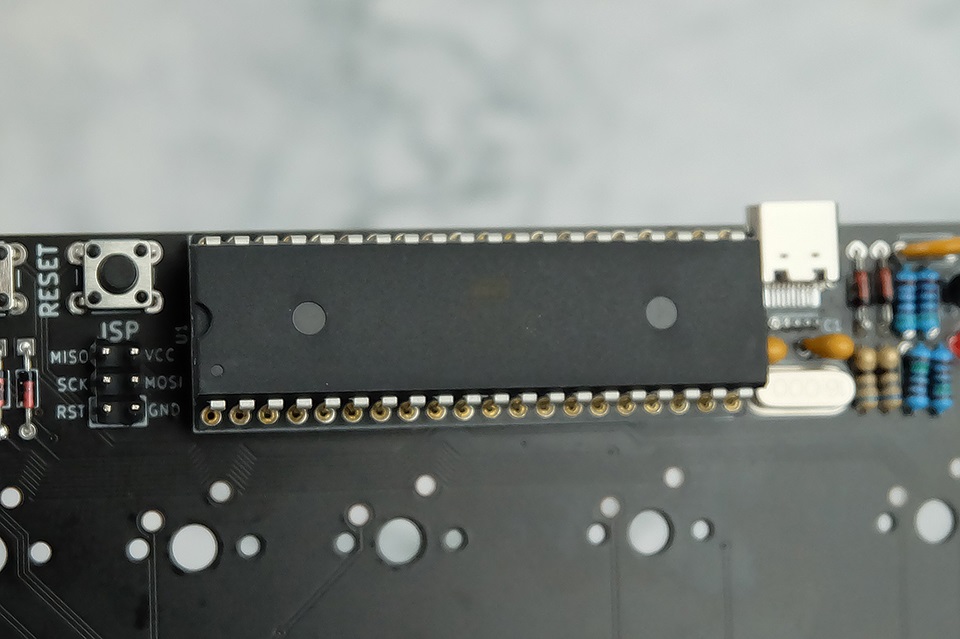
2x3 MALE HEADER
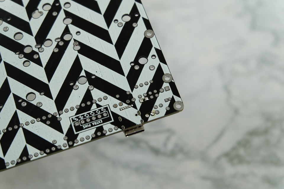
Next is the 2x3 male header from the bag of loose components. Insert it into the 2x3 hole marked ISP underneath the RESET button. Use tape to secure it to the PCB before flipping the PCB over and soldering. Remove the tape afterwards.
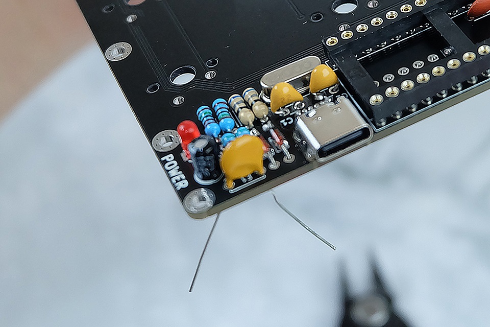
FUSE
Finally, the fuse. Remove the fuse from the tape and insert it into the component marked F1.
I'm not sure if this is the correct way of doing it, but it certainly looks better in my opinion. Mount the fuse such that the head is flush to the PCB.
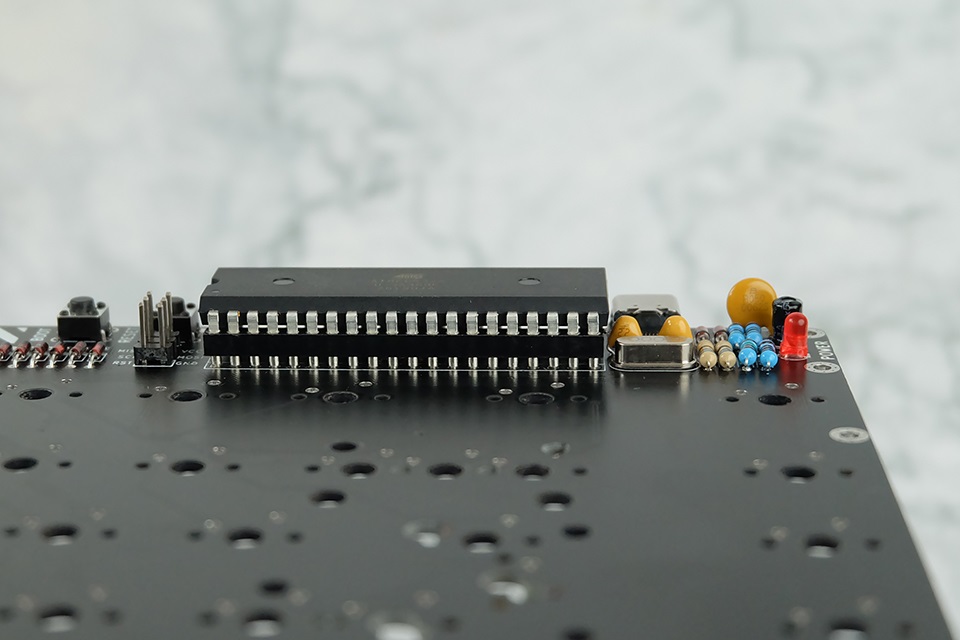
ATMEGA32A
Finally, grab the ATmega32A and mount it on the IC socket. Orientation is important!. Align the U-shaped marking to the U-shape portion of the socket (assuming you aligned it correctly). Make sure all the pins are aligned to each socket. If you press while misaligned, you will bend a pin.
Testing the PCB
Now that you've assembled the PCB, you're ready to test it out! As mentioned, all the chips come with VIA firmware already. You can load up VIA and test out the keypresses by shorting the switch holes with tweezers. As of this writing, the pull request for Herringbone had not yet been merged to VIA. Instead, download this JSON file, load up VIA and enable the Design tab, and load the JSON file you downloaded.
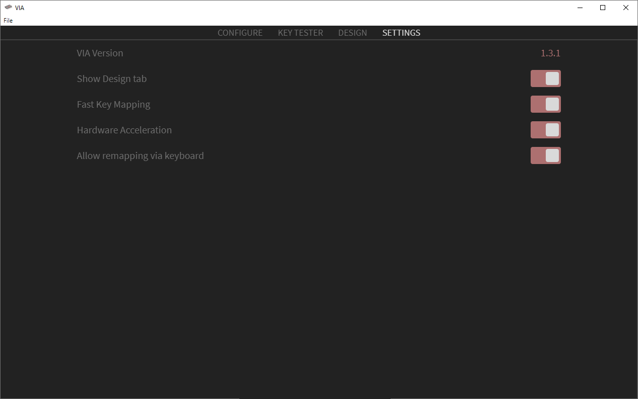

Once the pull request has been merged, this should just be plug and play.
Flashing the PCB
All the PCBs now have VIA supported out of the box; you will no longer need to flash the firwmare to update the keymap. Simply download the VIA software and remap your keyboard.
In case you do want to flash the firmware with something else, there is QMK Configurator support.
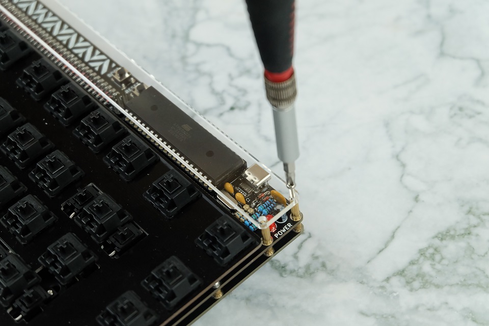
To flash firwmare, hold the BOOT button located next to the microcontroller and plug in your USB cable. Run QMK Toolbox and it should detect the keyboard and QMK Toolbox should report USBAsp device connected.
In Windows, if it's detected but there's a driver error, install the QMK drivers. This should have been done at first run of QMK toolbox, but if it didn't the URL is available.
After detection, click Open in QMK Toolbox and select the firmware file you want to flash (from either VIA or Configurator). Select atmega32a as the MCU on the upper right. Hit Flash, wait for it to finish, and you're done!
Low Profile Assembly
NOTE: The following section applies to low profile kit owners.
Grab eight M2×5 brass standoffs and eight M2×4 screws and install them on to the main PCB with the standoffs on the bottom side and the screws on the top side.

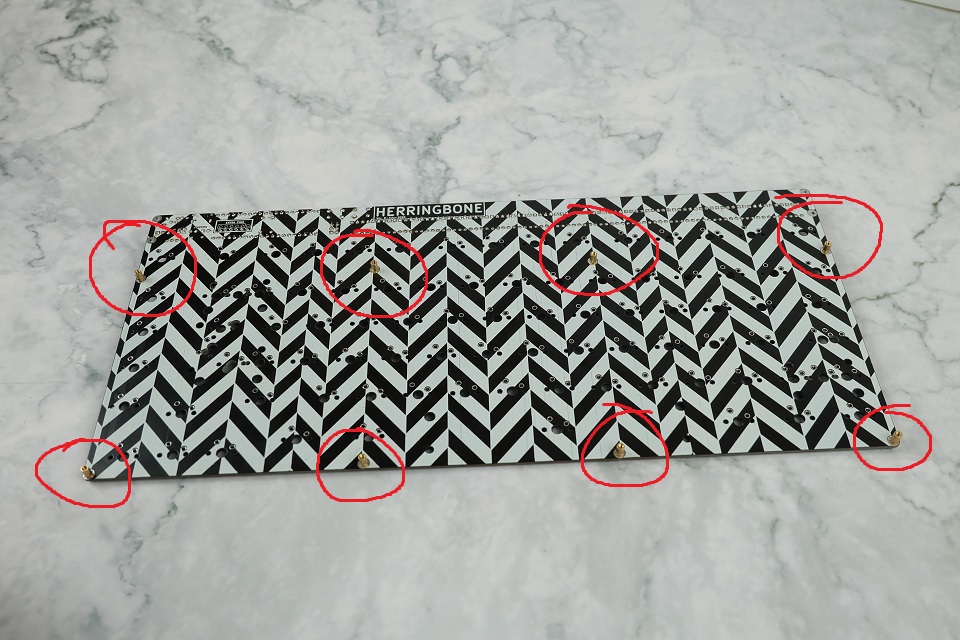
You will not be able to access these after the switches are installed, so screw them in as tight as you can.
Next, grab four M2×5 standoffs and four M2×10 standoffs and install them in the last remaining holes in the upper section of the main PCB.


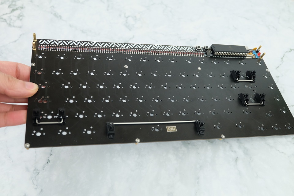
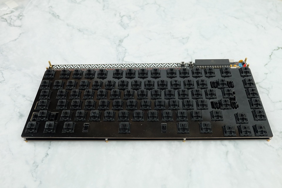
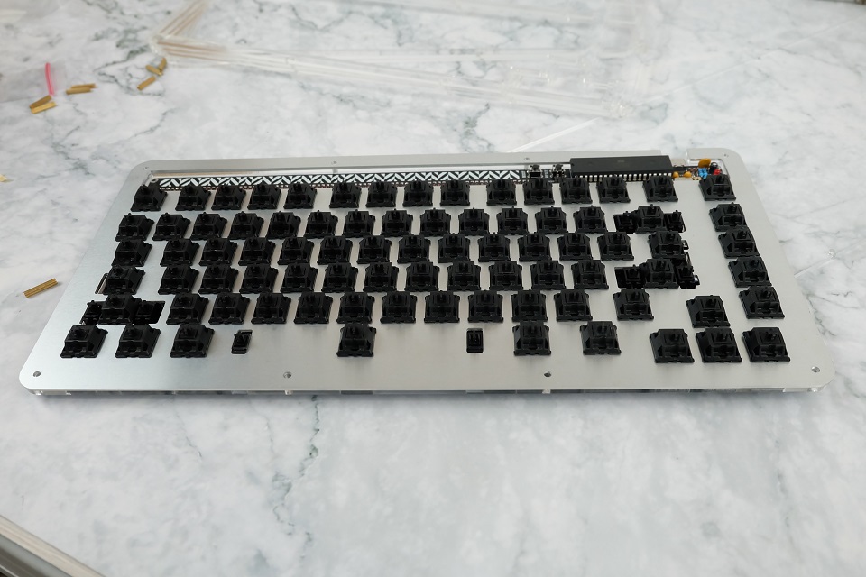
Now you're ready to assemble your keyboard like normal: install your stabilizers, install the switches to the plate, and solder the switches to the PCB.

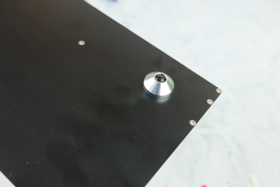
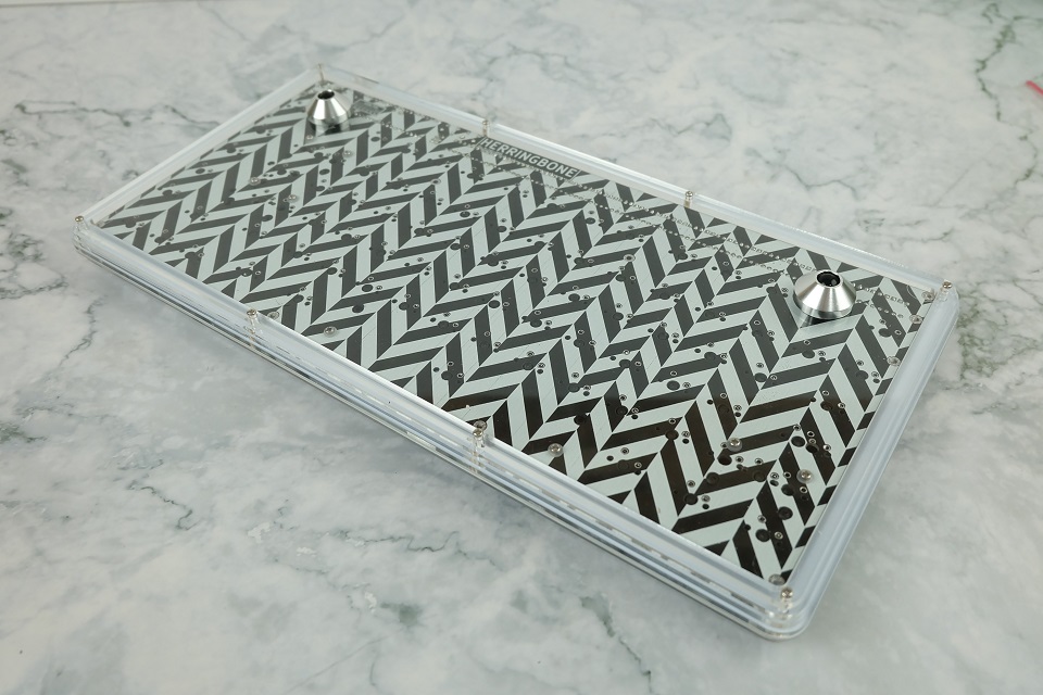
If you have aluminum cone feet, install it now to the bottom PCB. If you think the herringbone pattern is too noisy, you can flip the PCB around to have a clean black-only or white-only look.

Next use the remaining M2×4 screws to install the bottom PCB to the standoffs. Be careful not to loosen the bottom and middle standoffs because like I mentioned, there is no way for you to access those after the switches are installed.
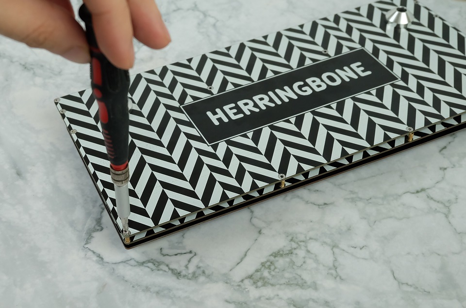
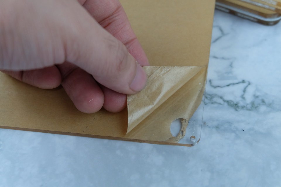
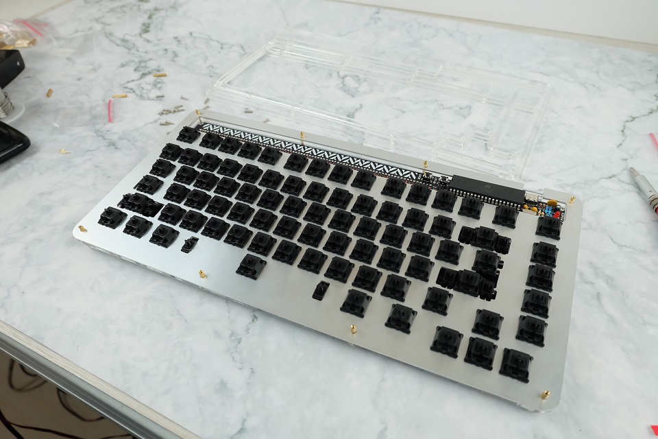
Finally, peel the acrylic cover, and install it on top of the tall standoffs using the remaining M2×8 screws. Be careful about static electricity build up when peeling the protective paper from the acrylic piece!
Finally, install your keycaps and you're done with the build!
High Profile Assembly
NOTE: The following section applies to high profile kit owners.
With the acrylic pieces separated, go ahead and peel the protective films from every layer. Again, be careful about static electricity build up when peeling the protective paper!

Install the stabilizers on the main PCB, place your switches into the aluminum plate and place the 3mm support layer underneath the aluminum plate. Everglide/Durock stabilizers should fit but it's still a bit more tight than I'd like and would require a bit of finagling. Solder the switches in.
Install the aluminum cone feet now if you have any. Place the bottom layers on top of each other.
Mount the PCB assembly on to the layers. Tolerance around the holes are a bit tight as well, so just finagle your way so the standoffs will go in.
Mount the rest of the layers and then screw them on using the M2×8 screws, and you should be done!


And now you're done! Fit the keycaps in and you should be good to go.
Glamour Shots


Remarks
Thanks to everyone who participated in this group buy! This was a fun project to design and make.